
PPMS Hall measurement package comparison
Use the guarded insert alone or with the high-resistance Hall measurement package.
| High resistance up to 200 GΩ | Standard resistance up to 10 MΩ | |
|---|---|---|
 |  | |
| Benefits | Benefits with M91 + Lake Shore guarded insert:
| Benefits with M91 integration:
|
| Resistance range | 10 mΩ to 200 GΩ | 10 mΩ to 10 MΩ |
| Integration | M91/PPMS integration with low noise, fully guarded insert | M91/PPMS integration with breakout box |
| FastHall model | M91-HR (high resistance) | M91 (standard) |
| FastHall excitation | Current source, voltage source | Current source |
| Sample mounting | Lake Shore sample board | PPMS sample puck |
| Signal path | Fully guarded (internal coaxial) from instrument to sample | Standard twisted pair wiring |
| Mobility | 106 cm2/(V s) to 0.001 cm2/(V s) | |
| Sample types | Supports van der Pauw and Hall bar samples | |
| Temperature sensor | Integrated Cernox® temperature sensor local to sample | |
| Control software | FastHall’s MeasureLINK® software for Hall measurement control integrates easily with the PPMS MultiVu™ application software | |
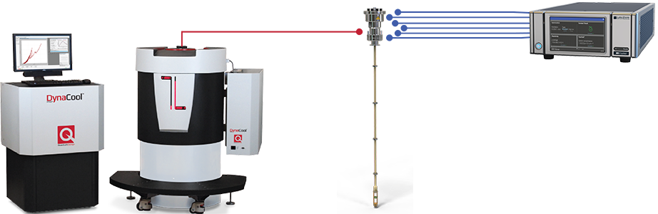
High-resistance package — PPMS/M91 integration via Lake Shore guarded insert
Diagram 1: PPMS connected to the M91 with the guarded insert
Features
- Fully guarded from instrument to sample for ultra-low noise measurements
- M91-HR resistance measurements up to 200 GΩ
- Samples mount to consumable Lake Shore sample carrier boards (also pin compatible with Quantum Design sample carrier boards); 12 are included
Specifications summary
| Triax center conductor leakage current (base temp, typical) | <500 fA at 10 V (guarded configuration) |
|---|---|
| Max current per pin | 100 mA |
| Max voltage between any 2 pins and insert body | 50 V DC, 25 VAC RMS, 35.3 V peak |
| Operating temperature range | 1.8 K to 400 K |
Sample connections
Diagram 1 generally shows how the PPMS/M91 connection is made via the Lake Shore guarded insert (Diagram 2).
The M91 supports both van der Pauw (4-connection) and Hall bar (6-connection) geometries. These samples are wired to the Lake Shore sample board (Diagram 3). The sample board then snaps into the sample insert board located on the probe (Diagram 4).
When the guarded insert is loaded into the PPMS, these sample connections are fully guarded up to the M91 via triaxial cables (included in kit). The integrated Cernox® sensor connections go to the PPMS, enabling temperature readings directly through MultiVu. Diagram 5 shows a close-up view at the working end of the insert.
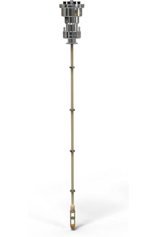
Diagram 2: Lake Shore guarded insert
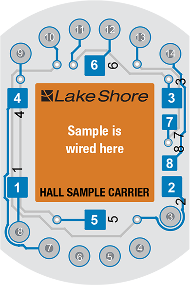
Diagram 3: Sample carrier board
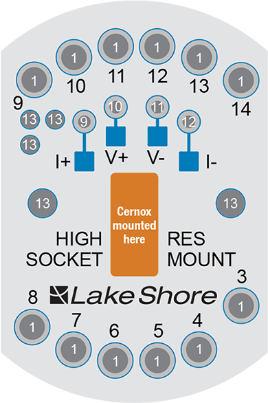
Diagram 4: Sample mount board
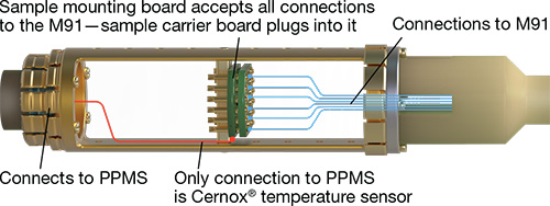
Diagram 5: Guarded insert connections
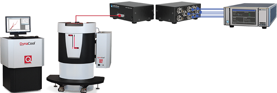
Standard resistance package — PPMS/M91 integration via Lake Shore breakout box
Diagram 6: PPMS connected to the M91 via breakout box
Features
- Compatible with the Quantum Design PPMS puck
- M91 resistance measurements up to 10 MΩ
Sample connections
The M91 supports both van der Pauw (4 connections) and Hall bar (6 connections) geometries. These samples should be wired to Quantum Design’s PPMS sample puck as shown in Diagram 2. When inserted into the PPMS, these sample connections are present on the LEMO connector on the side of the PPMS. The M91‑TRIAX‑DB25 breakout box enables these pins to connect to the M91. Six triaxial cables are included in the kit. Note: guarding is only up to the breakout box.
| Gray LEMO (puck) pins | FastHall triaxial |
|---|---|
| 3 (CH 1, I+) | 1 |
| 7 (CH 2, I+) | 2 |
| 8 (CH 2, I-) | 3 |
| 12 (CH 3, I-) | 4 |
| 4 (CH 1, I-) | 5 |
| 11 (CH 3, I+) | 6 |
| 10 (CH 2, V-) | AUX 1 |
| 9 (CH 2, V+) | AUX 2 |
| 6 (CH 1, V-) | Measure common |
Note: Internal jumper on measure common: Gray LEMO pin 6, puck CH 1, V-; P1-user bridge D shield, pin 13

Diagram 7: Pinning for PPMS sample puck